A deep-dive into the topic of zero-trust architecture with a look on the history of zero-trust, an implementation example as well as the questions and challenges that arose during its implementation.
Introduction
In a global world that forms an ever-closer bond based on growing digital solutions also cybercrime and cyber-attacks are on the rise. Starting in 2001 we can observe a constant rise of both the victim count and the respective financial losses. Statistics indicate that there have been 2,200 attacks per day in 2022, with a cyber-attack happening every 39 seconds on average targeting both individuals as well as corporations (Link: https://www.getastra.com/blog/security-audit/cyber-security-statistics/).
A number most likely to increase in the years to come as applications get more interconnected with partners evolving into ecosystems serving ever more use cases and the rise of AI allowing for more sophisticated phishing and social engineering attacks with fewer resources. Up to the point where oneself can do everything right (using strong passwords and password managers, leveraging a second factor for authentication, etc.) but still receive bogus phone calls and text messages due to a data leak at your phone plan provider. Which then results being threatened by someone apparently working for Europol / Interpol or the FBI with a police investigation or to be a relative in dire need of cash that obviously needs to be transferred via a cash sending mechanism and cannot simply be picked up by said relative (remember the police investigation mentioned…). Sounds familiar?
With that being said a paradigm shift is happening in the world of security engineering that tries to combat the constantly-growing number of attacks. The goal is no longer to keep the attacker out, but rather build your applications, ecosystems and entire corporate architecture in a way that assumes a breach has already happened and limits the amount of damage the attacker is able to cause.
The word coined for this is a “zero-trust” architecture that we have been able to help establish in one of our last projects for a German retail bank. In the following paragraphs we would like to dive deeper into this topic, the history of zero-trust, our implementation as well as the questions and challenges that arose during its implementation.
Setting the scene
For a long time, IT departments ran servers in their own data centres where they hosted applications that had been either self-developed or bought off the shelf and configured or customized to the needs of their organizations. Those applications were accessed by employees working on terminals and workstations located within the companies‘ offices and branches to perform their everyday tasks and serve their customers.
Not only with the Covid pandemic but long before, this working model has seen significant changes:
- Knowledge workers started to work from anywhere, be it from the office, their home, or a camper located at the beach (ranked least to most favourite working place, at least for us).
- Commodity applications are no longer acquired and self-hosted but hosted by the vendor itself, licensed and accessed via a browser (SaaS) to reduce complexity of one’s own IT landscape.
- Machinery has become somewhat intelligent or at least more tightly monitored by IOT-Devices that constantly stream data via the internet to the manufacturers allowing for predictive maintenance.
Today’s organizations need a new security model that more efficiently adapts to the complexity of the modern environment, embraces the hybrid workplace, and protects people, devices, apps, and data wherever they are located.

1. Perimeter security
“Traditional” IT if you’d like to call it that way, works like a fortified castle with a draw bridge. Everything that is inside the perimeter is considered an ally with more or less possibilities to access all servers and applications running within that perimeter. Everything outside the perimeter is considered to be evil and needs to be kept out. Such a perimeter defence most of the time consists of several layered mechanisms that comprise the entire socio-technical system i.e. not only hardware and software is used to keep intruders out, but also employee training as users represent the first line of defence but also the primary source of threats due to simple carelessness or deliberately malicious intent. To cross the chasm into our castle usually a DMZ or a VPN is established as a metaphorical gate bridge that allows traffic to flow in and out the perimeter to allow outside users such as customers to access the applications such as an Online Banking or an Insurance App.
In a distributed, cloud-native world perimeters no longer work as every outside connection to a SaaS provider pokes another metaphorical hole into our castle walls eventually making it look more like a fine-aged swiss cheese than an actual fortress. Our “new” paradigm trying to tackle this modern reality is called “zero trust”. Zero trust performs a mindset shifts and assumes that there is no 100% secure system but rather focuses on resiliency and to contain breaches to their least amount of possible impact while still maintaining a working IT environment to serve customers and employees alike.
Defining the Zero Trust paradigm
Zero Trust is built on three fundamental principles that all are interconnected:
- Assume a breach: Hackers will make it into your system at some point in time, there is no 100% security. We therefore want to reduce their blast radius i.e. the amount of damage they can cause as much as possible. This is sometimes exaggerated to the point where even while designing a system you assume that you have already been infiltrated. This follows the defense in depth paradigm but takes it to a whole new level.
- Least privilege: Each user (be it a technical user such as a service account or a natural person) as well as each workload only receives a very slim set of permission. The exact amount being as much as required to perform the underlying use-case. This arises from the segregation of duties paradigm but enhances it by focussing on breaking down permission-receiving entities into their most atomic sub-parts. To state an example this means we no longer have one technical user for a whole system but rather a myriad of technical users that in total make up the permissions our entire system requires.
- No more perimeters: We no longer establish a trust perimeter as described above for “traditional” IT i.e. there is no longer a distinction between “inside” and “outside” our organization, but an enforcement of explicit authentication (AuthN) and authorization (AuthZ) of each workload at every hop within our system for it to gain access to any resource. Additionally, this explicit trust is never permanently given. The workload needs to reestablish this trust with each new request for example by providing a signed token that can be dynamically verified for authenticity, validity and context.
These principles move protection away from a no longer existing (network) perimeter and much closer to the actual running workload focussing on the application and its data itself.

2. NIST-Model
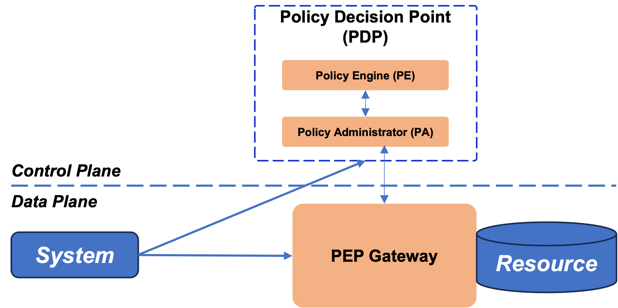
NIST within its Special Publication 800-207 „Zero Trust Architecture“ (ZTA) has described a reference architecture that nicely depicts the different components within such an architecture. Nevertheless, it is important to keep in mind that these kinds of components are just an example. The exact implementation is always depending on the organization and systems for which it is drafted as well as the integration with their partners.
Important are two (new) components, a Policy Decision Point comprised of a Policy Engine and a Policy administrator usually running in a sort of control plane and a Policy Enforcement Point running in the data plane of the workloads itself:
- The Policy Engine (PE) is responsible for the decision if access to a resource is granted or prohibited for a certain workload at a specified point in time.
- The Policy Administrator (PA) enforces this decision by establishing and/or
shutting down the communication path between a subject and a resource
- The Policy enforcement point (PEP) at which the above-mentioned decision is eventually enforced restricting access to the targeted resource
3. Policy decision point & PEP Gateway
In the following chapters we’d like to take you through our implementation that we have built to establish a zero-trust architecture but also highlight the challenges we faced while doing so.
Overview of our general setup
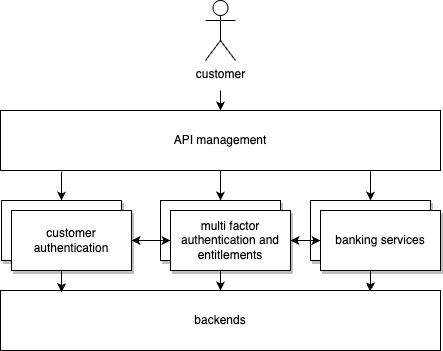
The online banking infrastructure that we have helped build with our client is semantically segregated into the three applications
- Customer Authentication,
- Multi Factor Authentication and Entitlements, and
- Banking Services
each serving one vital aspect that in total enables us to serve the banking use cases safely and securely to our customers and hosted within the Google Cloud (GCP) leveraging its services. Every application runs on two Google Kubernetes Clusters (GKE) in different regions to ensure resiliency in case of a regional outage within the GCP.
4. Architecture overview
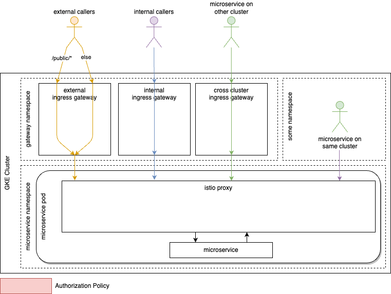
Anthos Service Mesh is used to abstract more security functionalities like TLS (Transport Layer Security) setup and trust management away from the developers, provide routing, cross cluster communication and service discovery. The abstraction is achieved via automatic sidecar proxy injection into every pod where a workload is running. This proxy will take care of incoming and outgoing traffic. The connection between the workload and the proxy will happen in the pod unencrypted, reducing the implicit trust zone mentioned in NIST’s concept to a minimum. The sidecar proxy, also known as the istio proxy, will terminate incoming mTLS traffic and upgrade outgoing connections to mTLS with a certificate that is provisioned and managed automatically. The certificate’s lifetime can be minimized to several minutes if enhanced protection against certificate misuse is required without breaking the architecture.
The mesh spans both clusters of an application, creating a multi cluster security mesh to improve resiliency. Designated entry points in the form of ingress gateways (essentially layer 4 load balancers managed by the service mesh) are created per potential origin of the call:
- Internal (from within the boundaries of the organization)
- External
- Cross Cluster
5. Initial architecture diagram
Communication to the cluster, between clusters and in the same cluster is protected by mutual TLS, providing an identity for both server and client in each connection. The service mesh can be configured to make use of a custom certificate authority as well as derive the needed trust from the latter. The identity of the last TLS client outside of the cluster is preserved at the ingress gateways by setting a header containing either the subject name or the subject alternative names to be used downstream. Existing headers are removed to prevent spoofing.
Zero Trust in motion
As described in the beginning, in a zero-trust architecture, no source or destination is trusted. Hence, for each call, identities and authentication for potential authorization need to be provided.
In our setup,
- verifiable identities will be provided via mutual TLS client certificates,
- authentication is realized through the usage of JWTs (Jason Web Tokens), and
- authorization is granted via Istio’s concept of authorization policies.
The next three sub-chapters will dive into details on the respective aspect within the aim of a zero trust Google Kubernetes Engine Cluster.
Identities – mTLS Client Certificates
Throughout the clusters and for all incoming traffic mTLS is enforced making sure that all connections are server and client authenticated, the data sent is protected from prying eyes via the encryption TLS provides, and the integrity is secured via state-of-the-art message integrity protection mechanisms.
To authenticate workloads and provide strong cryptographic identities, Anthos/Istio leverages SPIRE, an implementation of the SPIFFE APIs. The identities can be used for authentication and authorization in the following.
Disclaimer: In our specific case with distributed multi-kubernetes-clusters we need to differentiate between callers and consumers. Naively, the two concepts are the same, but within the underlying infrastructure, they can differ. If a certain microservice is called via the cross-cluster ingress gateway by a microservice from another cluster, the caller determined at the istio-proxy of the called microservice is the ingress gateway. The consumer though, is the microservice on the other cluster. Summarizing, since the identities are based on certificates extracted from the mTLS connection, the caller is identified as the last TLS terminating entity calling the resource whereas the consumer is the entity that initiated the request.
Implementation Details
To enforce mTLS throughout the cluster, create a peer authentication resource into the istio-system namespace with mTLS mode set to strict.
apiVersion: security.istio.io/v1beta1
kind: PeerAuthentication
metadata:
	name: enforce-mtls
	namespace: istio-system
	spec:
		mtls:
			mode: STRICT
Sidecar injection can be enabled by labelling the respective namespaces with the default injection labels, making sure each pod has a designated sidecar proxy that gets an identity by SPIRE and can properly authenticate itself within the cluster.
Authentication – JWT at the heart of it
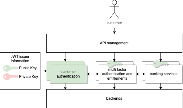
Authentication is realized by making use of signed JWTs that are granted after successful authentication against the IAM (Identity and Access Management) management solution running on the above-mentioned customer authentication cluster.
6. Architecture overview with keys
JWT, defined in RFC 7519, provides a solution to securely transmit information within a Json object. Information within the token is digitally signed using state of the art asymmetric cryptographic primitives. Public keys need to be distributed securely to all clusters that are configured to accept the respective token.
Example: A caller that wants to call a protected endpoint will authenticate against the designated authentication system. After successful authentication the JWT issuer will produce a token, containing further details like, but not limited to,
- Issuer ID – Who issued the token
- Audience – Who should accept the token
- Expiry – How long the token is valid
- Audit Tracking – Debugging and audit trails
- Session ID – Session handling
This token will be signed by the issuer using the private key and then handed over to the caller. The caller can now use the token within the defined timeframe to call the protected endpoint, which will use the public key of the issuer to validate the token. If the token is valid, i.e.
- the contents can be mapped to the signature and
- the signature can be verified via a public key from the trust store,
and the information contained is verified, i.e.
- the audience matches the protected endpoint’s infrastructure component ID and
- the token has not expired
the call will be processed, followed by downstream authorization mechanisms.
In the Anthos Service Mesh this verification is done in the configured access points of the cluster, the ingress gateways, and within the istio-proxies that exist in each pod and provide the mentioned abstraction regarding e.g. mTLS, service discovery or in our case JWT validation for microservices as depicted in initial architecture diagram.
Implementation Details
Istio’s request authentication resource can be configured within the istio-system namespace to verify JWTs with keys provided as Json Web Key Sets. Further restrictions to claims like audience can be set.
apiVersion: security.istio.io/v1beta1
kind: RequestAuthentication
metadata:
	name: req-authn-for-all
	namespace: istio-system
spec:
	jwtRules:
	- issuer: "issuer-foo"
	  jwksUri: https://example.com/.well-known/jwks.json
Authorization – Traffic Restrictions via Authorization Policies
With the authentication realized via the above-mentioned inter-play between the IAM-management solution, issued JWTs and validation within the clusters, this chapter will focus on authorization.
The Policy Decision Point has the following information at its disposal:
- Identity of the caller in form of a client certificate
- Identity of the initial cluster caller preserved within a header
- JWT specific information (can be extended if required)
- Signature of issuer
- Expiry
- Audience
- Session ID
Those details can be used in the Istio resource authorization policy to restrict traffic to those callers and consumers, that are eligible to query the respective service. We extend our architecture that already checks JWTs with authorization policies at strategic points within the communication between the caller and the callee as seen in Architecture-Wave-2.
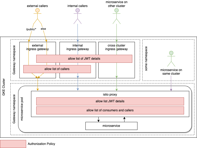
7. Architecture-Wave-2
On the gateway level, we restrict the communication to clients that own valid certificates from a trusted authority. The subject or one subject alternative name of the client certificate must be on the allow list of callers. In addition to that, the request must own a valid JWT verified as described previously.
Within the istio-proxy of our called microservice we enforce the callers to be one of the ingress gateways via the ID provided by the mTLS within the cluster. The initial cluster caller, our consumer, that is preserved within a header must be present on the allow-list, adhering to the principle of segregation of duty and least privilege. Both restrictions will be enforced via an authorization policy deployed with each workload. This policy additionally enforces a valid JWT from the issuer-key mapping defined in request authentication restricting further claims e.g. audience as required.
Rollout – Bringing Zero Trust to Life
Migrating from an open environment to a more restricted and regulated one bears various challenges. The approach must be secure and resilient but on the other hand scalable and easily configurable at the same time. The migration itself must not hinder ongoing development or even production while the fallout during migration must be minimized.
Hence the migration to a Zero Trust enabled Kubernetes Multi-Cluster environment can be split into three steps:
- Baseline – JWT validation, allow-list of JWT issuers and audience checks
- Wave 1 – Allow-list of cluster external callers validates at gateway
- Wave 2 – Allow-list of cluster-external and –internal consumers validated at the istio sidecar proxy
Baseline – JWT
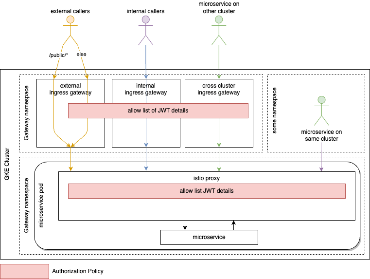
8. Architecture-Baseline
To establish a minimum set of security controls, JWT validation needs to be configures at the access point of the cluster and for cluster internal communication. The latter makes sure, that the cluster evolves from the old days of peripheral security to zero trust.
Wave 1 – Cluster external Callers at Gateway
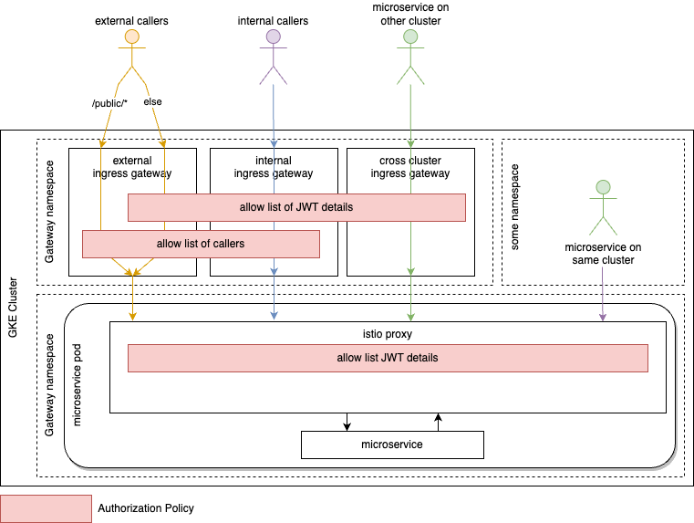
9. Architecture-Wave-1
The gateways are segregated by use case as elaborated earlier. Applying this approach enables us to implement context aware and context adjusted security mechanisms. Authorization policies for the respective audiences can be strict or lenient based on their expected security maturity. Once the audience and their identities are known, the access can be restricted on the boundaries of the cluster by only accepting callers coming from known sources defined in the mTLS client certificate from a trusted certificate authority.
Since the gateway segregation is part of the initial design, restricting callers this way only reveals microservices that did not adhere to agreed concepts. As a fix, microservices need to use the proper gateway and consumers of respective microservice need to change the called endpoint URL accordingly. This can easily be detected and mitigated in the lower environments of the staging chain.
As a compliance bonus, the cluster owner always has a list of potential consumers for any audit purposes or security tests.
Wave 2 – Consumers at Istio-Proxy

7. Architecture-Wave-2
Whereas most of the previous steps during the migration to zero trust relied mainly on central teams, the last step requires an effort by the teams developing and consuming microservices.
To support those teams from the beginning to reduce friction, resistance, and issues, a baseline of current callers can be created for the teams. An envoy filter can be deployed temporarily that logs calls including relevant identity information implementing a dry mode for teams to assess. Envoy filters can be used to change or act on requests or responses via Lua code. Logging a warning message with information on
- Caller ID,
- Consumer ID, and
- Request Type (cluster internal/external, another cluster)
microservice teams can populate the initial allow-list before the restrictions are enforced. Simple extraction scripts ease the process.
Once the teams have generated their baseline from the logs, the specific authorization policies must be deployed. A mandatory helm chart specific to deployment in the environment containing a template for an authorization policy that is fed with values provided by the team was leveraged to shield the complexity of authorization policies from the teams.
NIST Concept Mapping
To map the presented concepts to the described NIST Zero trust scheme, the calling actor owns the role of the system. The PEP-agent is represented by the istio-proxy, querying the istio core system as the policy administrator. Based on the existing authorization policies as policy engine, the istio core system will grant or deny the access. The decision is enforced back on the istio-proxy as the PEP-gateway.
Result and challenges
The above-described architecture is as of now in use by our client and helped to enable not only a zero trust architecture but also more confidence in the overall implementation in light of current cyber threats. With the chosen approach our client now possesses the ability to simply add additional applications or singular services to its architecture that can leverage the same mechanisms to establish trust between its workloads.
With our implementation we faced several challenges that were mainly due to the nature of the solution development itself. While the online banking in question was a green field implementation as part of a lighthouse project to establish the Google Cloud at our client the migration to a full-on zero trust approach can be considered brown field. Most of the used components such as the central authentication application, the entitlement system as well as main parts of the JWT-authentication solution had already been built. Responsible teams where mainly focused on building additional customer functionality into their systems and where reluctant to modify their workloads to comply with the above requirements of a ZTA.
These opposing priorities we helped to overcome by letting the whole solution run a couple of weeks in a dry run mode and compiling an initial allow list from sniffing the logs for denies. Feature teams responsible for service providers simply needed to sign off a given list of service consumers highly simplifying their initial time invest and lowering the barrier for subsequent fine tuning.
Eventually there are still some parts missing that we would like to have introduced mainly due to outside limitations beyond our influence. To name one would be a general egress gateway to route all traffic to our backends via a central point to enforce policies. Sadly, this is currently not possible due to several restrictions in the legacy backends and especially the networking architecture that simply does not allow us to safely develop and test this solution. Again, highlighting how delicate the rollout of a ZTA is and how high the possible impact.
Summary
Based on the number of current threats highlighted in our introduction in conjunction with a more and more connected world leveraging distributed, cloud-native architecture it is easy for one to conclude that implementing a zero-trust architecture is required for every organization. As we are both convinced that in the long term every company should move to a zero-trust setup especially focussing on the “assume breach” part of the paradigm and away from a sole perimeter-based defense there is more grey to it than being a simple black or white decision. Mainly as most breaches still result from careless users.
Implementing a zero-trust architecture is a lot of work and requires a structured and planned approach to be a success. Especially if one takes into consideration that a bug within the zero-trust enforcement or a faulty implementation can have a catastrophic impact of an unseen magnitude for the organizations systems as no connection should be possible anymore.
The initial focus needs to be on creating an inventory of your own infrastructure, services and applications, their identities, use cases and requirements to properly plan out the implementation. During the implementation a dry mode is essential to avoid blocking any business-critical use case in production due to missing transparency of non-explicitly stated connections as well as missing commitment and time capacity for all teams to implement the necessary pre-requisites. Finally the zero trust approach is once implemented never in a finished state but should be dynamically modified (which is now much simpler compared to the pre-work that needed to be done) and adjusted to react to new developments or unforeseen attack patterns. ddd

